How to Choose the Right GI Cable Tray for Your Project?
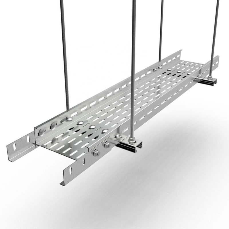
When we started shipping GI cable tray systems to Southeast Asia and Africa, one pattern kept repeating: buyers picked a model first, then tried to make it fit the project.
Choosing the right GI cable tray means matching the coating type, tray style, load capacity, dimensions, and support span to your project’s environment, cable load, and future expansion needs — not simply picking the cheapest or thickest option available.
The truth is, about eighty percent of the selection errors I see come from working backwards — choosing a product number before defining the system requirements. Let me walk you through the four decisions that actually matter.
Which Type of GI Coating Should I Choose for My Project’s Specific Environment?
A lesson we learned early in our export business: two projects in the same country can need completely different GI finishes because one site is a dry warehouse and the other is a coastal water treatment plant.
The right GI coating depends on your installation environment. Pre-galvanized steel suits dry indoor spaces with low corrosion risk, while hot dip galvanized steel is essential for outdoor, humid, coastal, or chemically aggressive environments where a thicker zinc layer prevents premature failure.
Understanding the Three Main GI Coating Types
"Galvanized" is not a single specification. It is a family of finishes, and each one performs differently. Here is a quick breakdown.
| Coating Type | Zinc Layer | Best Environment | Relative Cost |
|---|---|---|---|
| Pre-galvanized (GI) | Thin, applied before forming | Indoor, dry, controlled climate | Lowest |
| Hot dip galvanized (HDG) | Thick, applied after fabrication | Outdoor, humid, coastal, chemical | Medium–High |
| Electro-galvanized (EG) | Very thin, uniform appearance | Light indoor, decorative, temporary | Low |
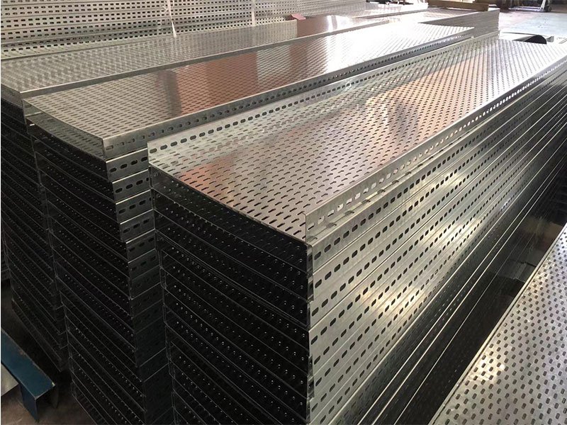
Pre-galvanized trays are the workhorse of commercial buildings, control rooms, and assembly lines. The zinc coating is applied to the steel coil before the tray is cut and formed. That keeps cost down and gives a clean finish. But the cut edges and weld points are exposed, so corrosion resistance is limited in wet or aggressive conditions.
Hot dip galvanized trays go through a molten zinc bath after fabrication. Every surface, edge, and weld gets coated. The result is a thicker, more durable layer that self-heals minor scratches. When we quote projects for water treatment plants or outdoor solar farms, hot dip galvanized is almost always the right call.
How Environment Drives the Coating Decision
Think of it this way: the coating is your tray’s first line of defense. If the environment is mild, a thin defense works. If the environment is harsh, you need a thick one.
| Environmental Factor | Pre-Galvanized OK? | Hot Dip Galvanized Recommended? |
|---|---|---|
| Indoor, dry, climate-controlled | Yes | Optional |
| Indoor, moderate humidity | Borderline | Yes |
| Outdoor, sheltered | No | Yes |
| Outdoor, fully exposed | No | Yes |
| Coastal or salt air | No | Yes |
| Chemical vapors or washdown | No | Yes, or consider additional coating |
I have seen projects where a buyer saved a few dollars per meter by using pre-galvanized trays outdoors. Within eighteen months, rust appeared at every joint. The rework cost was several times the original savings. That is why I always ask about the installation environment before quoting a finish.
Temperature, UV, and Other Overlooked Factors
Corrosion resistance is the headline concern, but environmental conditions include more than humidity. Temperature swings cause condensation inside trays. UV exposure degrades cable jackets faster in open ladder trays. Dust-heavy environments may favor solid-bottom or covered perforated trays to keep debris off cables. Each of these factors can shift the coating and tray-type decision.
The bottom line: define the environment first, then choose the coating. Never assume all GI cable trays perform the same way in every setting.
How Do I Determine the Correct Size and Load Capacity for My Cable Tray System?
One of the most common conversations I have with project contractors goes like this: "We need 300 mm wide trays." When I ask how they arrived at that number, the answer is often a guess based on the last project. That shortcut causes problems.
To determine the correct size and load capacity, calculate the total cable weight per meter, add the tray’s self-weight and any environmental loads, then verify the result against the manufacturer’s rated capacity at your planned support span — because width, depth, thickness, and span all interact.
Width: Start with Cable Diameter, Not Tray Catalog
The right tray width comes from the cables, not from a product list. Here is a simplified process:
- List every cable that will run in the tray. Record the outside diameter of each.
- For single-layer installations in a ladder cable tray, the minimum inside width equals the sum of all cable diameters plus required spacing.
- For solid-bottom trays, the sum of cable diameters should not exceed 90% of the available tray width.
- Apply the fill limit for your tray type and cable class — typically 40% to 50% of total available cable area.
- Round up to the next standard tray width.
Standard cable tray dimensions commonly range from 150 mm to 1200 mm in width and 25 mm to 200 mm in height. Common ladder tray widths in imperial systems include 6, 9, 12, 18, 24, 30, 36, and 48 inches.
Load Capacity: More Than Just Cable Weight
Load capacity is where many projects go wrong. The total design load includes three components:
| Load Component | What It Includes | How to Estimate |
|---|---|---|
| Cable load | Weight of all installed cables per meter | Sum of each cable’s published weight/m × quantity |
| Tray self-weight | Weight of the tray structure per meter | From manufacturer data or geometry-based calculation |
| Additional loads | Ice, snow, wind, maintenance access, vibration | Site-specific; safety factor of 1.5–2.0 is common |
A tray rated at 16.8 kg/m might seem generous for a cable load of 10 kg/m. But once you add tray self-weight and a safety factor, the margin shrinks fast. And if the support span is longer than the manufacturer tested for, the effective capacity drops even further.
Support Span Changes Everything
This is the detail that catches people off guard. The same tray can pass at a 1.5-meter support span and fail at a 3.0-meter span — even with identical cable load. Longer spans increase bending stress and deflection. In my experience, many field failures are not outright breaks. They are excessive sag that makes the tray look unsafe and makes future cable pulling difficult.
When we help buyers spec their cable management system, we always confirm the planned support spacing before recommending a tray gauge and side rail height. Increasing width alone does not solve every load problem. Sometimes the better fix is reducing the span between supports or choosing a deeper side rail for added stiffness.
Practical Rule: Size for the Future
A good rule of thumb is to target around 40% initial fill. That leaves room for future cable additions, maintenance access, and airflow. Wider trays generally outperform deeper trays for cable management, so increase width before depth when possible. And always choose the next standard size up rather than forcing a tight fit.
What Quality Certifications Should I Verify Before Purchasing My GI Cable Trays?
During a recent order review for a solar energy project in Africa, the buyer’s engineer asked for our compliance documentation before even discussing price. That interaction reminded me how much the industry has shifted toward verification-first procurement.
Before purchasing GI cable trays, verify compliance with relevant standards such as IEC 61537 for mechanical and electrical performance, NEMA standards for tray classification, and any local electrical codes like NEC provisions — plus confirm the manufacturer’s quality management certification and coating test reports.
Why Certifications Matter More Than Spec Sheets
A spec sheet tells you what a manufacturer claims. A certification tells you what a third party has verified. In international trade, the gap between those two things can be enormous. I have seen trays that looked identical on paper but performed very differently under load testing because one manufacturer cut corners on material thickness or zinc coverage.
Key Standards to Check
Here are the standards and certifications that matter most for GI cable tray procurement:
- IEC 61537 — Covers mechanical strength, electrical safety, and performance testing for cable trays and ladders. This is the international benchmark.
- NEMA standards (VE 1, VE 2) — Define tray types, load ratings, and testing methods. Widely referenced in North American and international projects.
- NEC (National Electrical Code) — Specifies which tray types are permitted for which cable types and locations. For example, single-conductor and Type MV cables must be installed in ladder or ventilated trough trays, and solid-bottom trays are restricted in certain hazardous locations.
- DIN 4102-12 — Relevant for fire resistance classification where European or German standards apply.
- ISO 9001 — Quality management system certification. It does not guarantee product quality by itself, but it shows the manufacturer has documented processes and internal audits.
What to Request from Your Supplier
When we work with EPC contractors and procurement managers, we provide coating thickness test reports, material certificates, and load test data as standard practice. Here is what I recommend you ask any supplier for:
- Material test certificates for the base steel (grade, thickness, yield strength).
- Zinc coating thickness reports — especially important for hot dip galvanized trays.
- Load test results at specified support spans.
- Copies of relevant certifications (IEC, NEMA, or local equivalents).
- Quality control process documentation, including inspection checkpoints.
If a supplier cannot provide these, that is a red flag. In my experience, the cost of verifying quality upfront is always lower than the cost of dealing with product returns, project delays, or on-site failures.
Code Compatibility: The Hidden Selection Filter
One point that surprises many buyers is that the "best" tray is sometimes determined by code, not preference. NEC provisions restrict solid-bottom trays in certain hazardous locations and require ladder or ventilated trough trays for specific cable types. If your project falls under these rules, your tray choice is partially made for you before you even look at a catalog. Always confirm code compatibility before finalizing your purchase.
How Can I Ensure My GI Cable Tray Selection Meets My Long-Term Durability Requirements?
A project director I work with in Singapore once told me his biggest frustration is not the initial purchase — it is the maintenance headaches that show up three to five years later when the wrong tray starts corroding or sagging.
To ensure long-term durability, match the GI coating type to the corrosion severity of your environment, verify that load ratings include a safety factor for future cable additions, plan support spacing to prevent long-term deflection, and leave at least 30% to 50% spare capacity for system expansion.
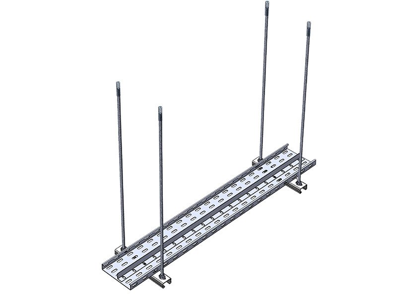
Durability Is a System Decision
Durability does not come from one feature. It comes from the interaction of coating quality, structural design, installation quality, and maintenance planning. A hot dip galvanized ladder cable tray installed with proper support spacing and adequate spare capacity will last decades. The same tray installed with supports too far apart, filled to 90% capacity on day one, and left without covers in a dusty outdoor environment will fail much sooner.
The Four Pillars of Long-Term Performance
Here is how I think about durability when helping buyers plan their cable tray installation:
1. Coating matched to environment. This is the foundation. Pre-galvanized for dry indoor. Hot dip galvanized for outdoor, humid, or corrosive. If the environment is extremely aggressive — think chemical plants or coastal industrial zones — consider additional protective coatings or alternative materials entirely.
2. Structural margin. Choose a tray gauge and side rail height that gives you headroom above the calculated load. A safety factor of 1.5 to 2.0 is standard practice. This accounts for installation impact, vibration, and the reality that cable loads almost always grow over time.
3. Expansion capacity. I recommend targeting around 40% initial fill and leaving 30% to 50% spare width for future cables. Projects that fill trays to near capacity during initial installation almost always face expensive retrofits within a few years.
4. Maintenance access. Ladder type cable tray and perforated cable tray designs make inspection and cable changes easier than solid-bottom systems. If your facility will need periodic cable additions or replacements, choose a tray style that supports access without dismantling the entire run.
Lifecycle Cost vs. Upfront Cost
The cheapest GI cable tray is rarely the most economical over a ten- or twenty-year project life. Here is a simplified comparison:
| Cost Factor | Low-Spec Tray (Cheapest Upfront) | Right-Spec Tray (Matched to Project) |
|---|---|---|
| Initial purchase | Lower | Moderate |
| Corrosion-related replacement | High (within 3–7 years in harsh environments) | Low (designed for environment) |
| Retrofit for expansion | High (tray too small or too full) | Low (spare capacity planned) |
| Maintenance labor | High (difficult access, sagging) | Low (proper support, open design) |
| Total lifecycle cost | Higher | Lower |
When I quote projects, I always present this comparison. Buyers who understand lifecycle cost almost always choose the right-spec option. The ones who regret their purchase are usually the ones who optimized only for the lowest line-item price.
Cable Tray Accessories and System Integrity
Long-term durability also depends on cable tray accessories — bends, tees, reducers, couplers, covers, brackets, and supports. Mismatched or low-quality fittings create weak points where corrosion starts, joints loosen, and cables shift. When sourcing your cable management system, make sure all accessories come from the same manufacturer or are verified as compatible. A tray system is only as durable as its weakest connection.
Future-Proofing for Smart Infrastructure
More projects now plan for future data density, IoT integration, and power upgrades. That means the GI cable tray you install today may need to carry cables that do not exist yet. Wire mesh cable tray is gaining popularity in data centers for exactly this reason — it is lightweight, easy to modify, and supports rapid reconfiguration. For industrial plants, a combination of ladder trays for heavy power runs and perforated trays for control and signal cables gives the best balance of strength and flexibility.
Conclusion
Choosing the right GI cable tray is a system decision. Match the coating to your environment, size for future growth, verify certifications, and plan for lifecycle durability — not just the lowest price tag.