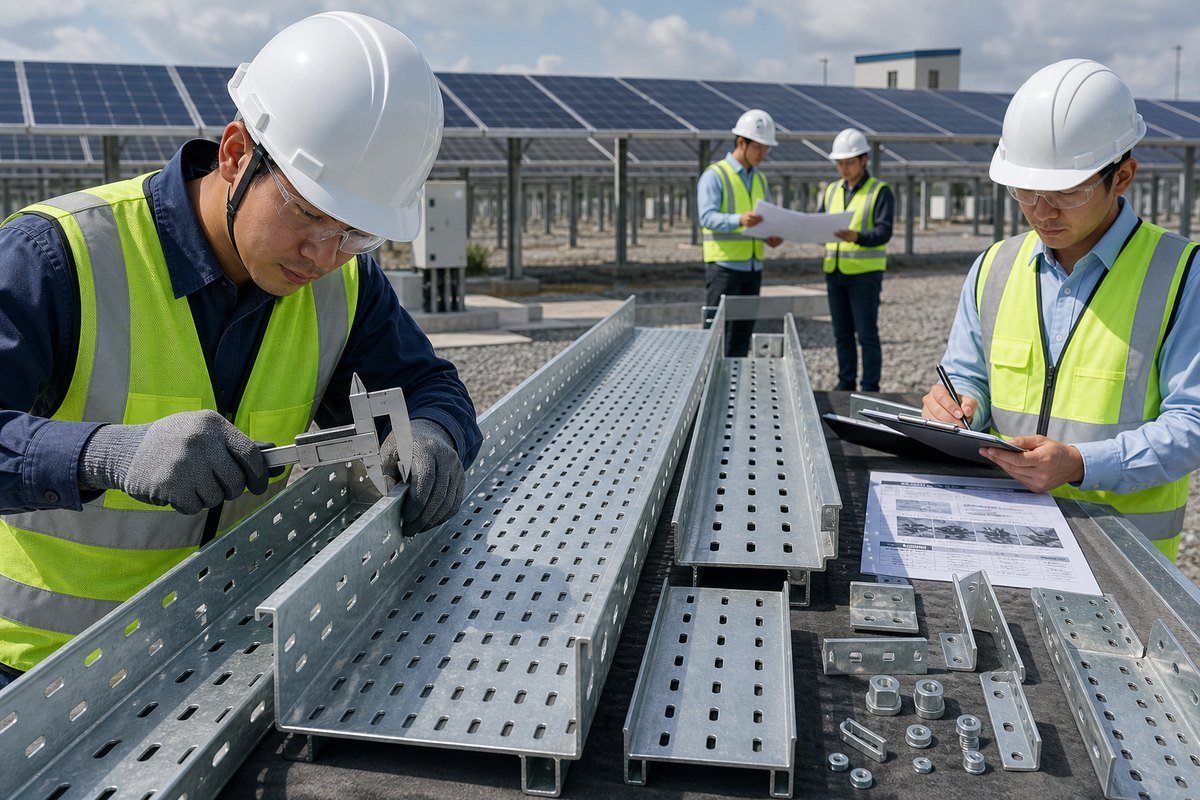
Choosing galvanized perforated cable trays for solar power projects looks simple until a coastal site starts rusting in year three. I have seen that happen, and on our production line we now flag every solar inquiry for environment checks first, because one wrong coating spec can cost an EPC contractor an entire warranty claim.
To choose galvanized perforated cable trays for solar power projects, match zinc coating thickness to site corrosivity, verify load capacity per IEC 61537 or NEMA VE 1, select perforation patterns with at least 40% open area for heat dissipation, and confirm the manufacturer provides material test certificates and third-party inspection.
That is the short answer. But each of those four checks hides real engineering decisions. Let me walk you through them one by one, based on what actually goes wrong in real projects.
How do I determine the right galvanized coating thickness for solar project durability?
A buyer from the Philippines once sent me photos of white rust blooming on trays supplied by another vendor after only 18 months near the coast. Our team traced it to thin pre-galvanized sheet used where hot-dip galvanized (HDG) steel was needed. That single photo shaped how I quote every solar project today.
Match zinc coating thickness to the site’s corrosion resistance class: pre-galvanized steel (around 20 microns) suits dry indoor use, while hot-dip galvanized trays per ASTM A123 (65–85+ microns) are required for outdoor solar fields, and C4–C5 coastal or industrial sites need thicker HDG or ZAM coatings.
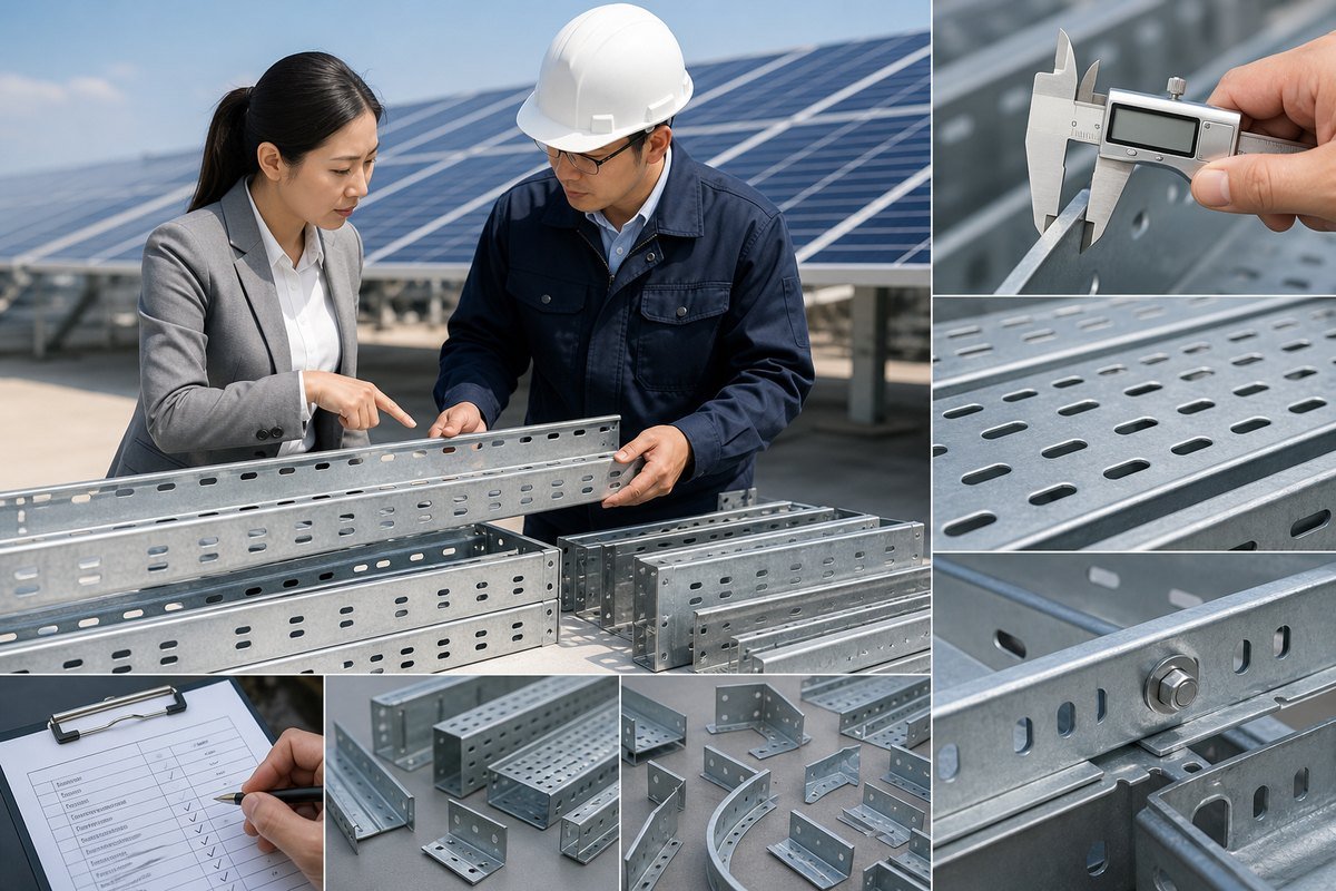
Zinc protects steel sacrificially. It corrodes first, so the steel underneath stays intact. The thicker the zinc layer, the longer the protection lasts. That is why coating thickness is the single most important durability decision for outdoor environmental conditions in solar farms.
Pre-galvanized vs. hot-dip galvanized
Pre-galvanized (GI) trays are made from steel coil that was zinc-coated before fabrication. The cut edges and punched holes expose bare steel. For a perforated tray 1, that means hundreds of exposed edges. Hot-dip galvanized trays are fabricated first, then dipped in molten zinc. Every edge, hole, and weld gets coated. For a 25-year solar plant, that difference is decisive.
Matching coating to corrosion class
Use the ISO corrosivity categories 2 as your guide. Here is how I frame it for clients:
| Corrosion Class | Typical Solar Environment | Recommended Coating | Approximate Zinc Thickness |
|---|---|---|---|
| C1–C2 | Indoor inverter rooms, dry inland | Pre-galvanized (GI) | ~20 microns |
| C3 | Rural ground-mount, moderate humidity | Hot-dip galvanized | 45–65 microns |
| C4 | Tropical, high humidity, near industry | HDG per ASTM A123 | 65–85 microns |
| C5 | Coastal, salt spray, chemical exposure | Heavy HDG or ZAM coating | 85+ microns or ZAM |
ZAM (zinc-aluminum-magnesium) coatings are worth considering for C4–C5 sites. They offer self-healing behavior on cut edges, which reduces the need for cold-galvanizing touch-up sprays on site. In our export experience to Southeast Asia, tropical humidity plus coastal proximity almost always pushes the spec toward full HDG. Do not let a low quote tempt you into GI trays for an open-field photovoltaic array. The replacement labor alone will erase any savings.
What perforation pattern and load capacity should I look for in solar cable trays?
The trade-off I weigh most often in our workshop is open area versus stiffness. Punch more slots and the tray breathes better, but it also deflects more under load. Getting that balance right is where perforated tray design either succeeds or fails in a solar field.
Look for perforation patterns providing roughly 40% open area for cable tray ventilation and heat dissipation, and verify load-bearing capacity against NEMA VE 1 or IEC 61537 test data at your actual support span, including allowance for future DC string cable additions.

DC cables in solar farms run warm under load, especially at midday peak generation in hot climates. Poor airflow forces ampacity derating 3, which means you pay for thicker cables. Good perforation solves this. The elongated oval slots you see on quality trays are not decoration. They allow air circulation under and around the cables, and they let rainwater drain instead of pooling.
Perforation pattern checklist
When you review a supplier drawing, check these points:
- Open area ratio of about 40% on the base for heat dissipation.
- Slot edges deburred or formed with a returned-edge design, so PV cable insulation is not nicked during thermal movement cycles.
- Symmetrical slot rows, so cable ties and clamps can be fixed at any point along the run.
- Side-wall perforations for drainage and for attaching drop-outs or dividers.
Load capacity is a span decision
Load capacity means nothing without the span. A tray rated for 100 kg/m at 1.5 m supports may deflect badly at 3 m supports. Perforated trays generally need closer support spacing than ladder trays. Ask for the manufacturer’s load-deflection curves tested per IEC 61537 4 or NEMA standards, then check them against your actual support layout.
| Factor | What to Verify | Why It Matters |
|---|---|---|
| Safe working load | kg/m at your span, not the catalog span | Prevents mid-span sag and cable stress |
| Deflection limit | Typically span/200 at rated load | Sag pools water and stresses joints |
| Future fill | 20–30% spare capacity | Utility-scale plants add strings in phases |
| Thermal movement | Expansion splice plates every 30–50 m | Steel trays move significantly in open fields |
| Steel thickness | 1.0–2.5 mm depending on width and span | Thin steel plus wide tray equals failure |
One more field-specific point: with bifacial modules 5, avoid oversized tray profiles routed directly under the panels. Wide trays create backside shading and cut the yield from ground-reflected light. Route trays along torque tubes or piles where possible, and keep the profile height low.
How can I verify quality control standards when sourcing from a cable tray manufacturer?
Last year, a Singapore project director told me his previous supplier’s trays arrived with zinc thickness far below the promised spec, and he only found out after installation began. We now photograph our coating-thickness gauge readings on every batch before packing, because trust in this business is built on documents, not promises.
Verify quality by requesting mill test certificates for raw steel, hot-dip galvanizing test reports confirming zinc coating thickness per ASTM A123, compliance documentation for IEC 61537 or NEMA VE 1, third-party inspection (TPI) before shipment, and evidence of prior large-project supply experience.
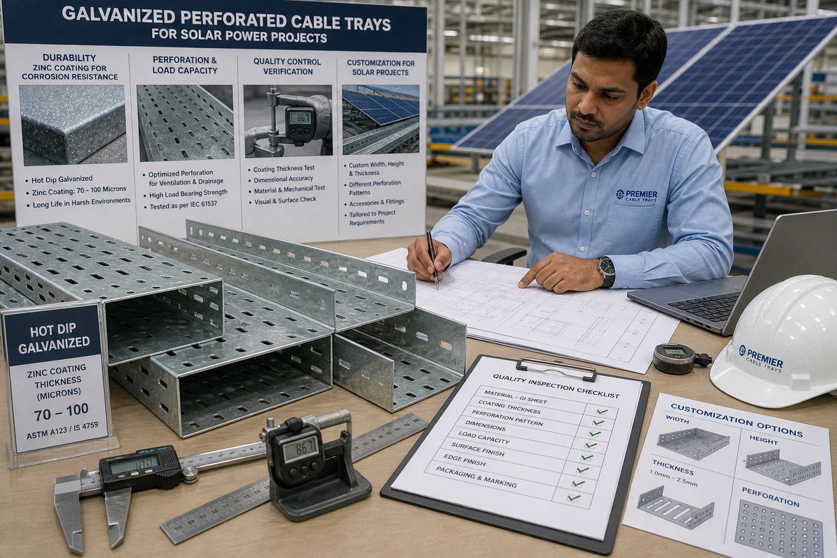
Quality control for cable trays is not complicated, but it must be systematic. A serious cable tray manufacturer will provide every document below without hesitation. If a supplier stalls on any of them, treat that as a warning sign.
The document trail you should demand
- Material Test Certificate (MTC). This traces the steel back to the mill and confirms grade, yield strength, and thickness.
- Galvanizing test report. This states measured zinc coating thickness, usually taken with a magnetic gauge at multiple points, referenced to ASTM A123.
- Standards compliance statement. Ask which clauses of IEC 61537 or NEMA VE 1 the product was tested against, and request the actual test data, not just a logo on a brochure.
- Third-party inspection. TPI before container loading catches dimension errors, coating defects, and packing problems while they can still be fixed.
- Full export documentation. Packing lists, dimensional reports, and photos of strapped, bundled stacks ready for shipment.
Judge the factory, not just the paper
Documents can be checked; habits must be observed. Ask for production photos or a video call walk-through. Look at how trays are stacked and strapped for sea freight—galvanized surfaces scratch, and bad packing means white rust in the container. Ask about production and delivery schedules in writing. In our own work supplying repeated orders to the Philippines national grid operator NGCP, the schedule commitment mattered as much as the product spec, because grid and solar projects run on penalty clauses. A supplier with real industrial project experience will talk comfortably about IFC drawings, hold points, and inspection notifications. A trader reselling generic stock will not.
What customization options do I need to consider for solar power project specifications?
An EPC engineer in Thailand once sent us an IFC drawing package with fourteen different tray configurations for a single solar plant. That project taught our small team a lasting lesson: solar sites are never uniform, and off-the-shelf trays rarely fit a real layout without waste.
Consider customization of tray width, height, and steel thickness to match cable fill; fittings such as bends, tees, and reducers; peaked ventilated covers for debris and snow; grounding and bonding hardware; expansion splices; and project-based fabrication directly from IFC drawings and specifications.
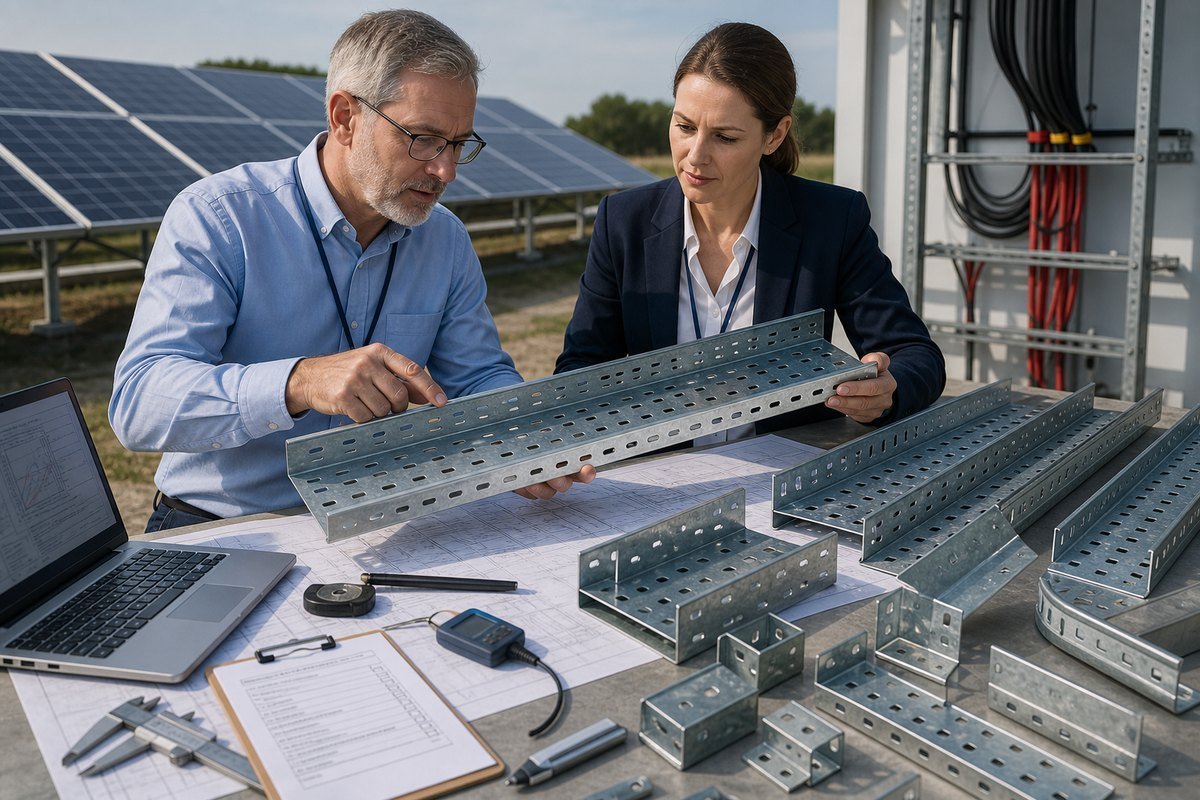
Customization is not a luxury on solar projects. It is how you avoid field modification, which destroys the zinc coating and slows installation. Here are the option groups I review with every solar client before production starts.
Dimensions and fill
Size the tray from total cable cross-sectional area 6 plus fill-ratio limits. Overfilling traps heat, complicates pulling, and blocks future expansion. For phased utility-scale builds, I usually suggest sizing for the final phase from day one. The steel cost difference is small compared with re-trenching cable routes later.
Fittings, covers, and accessories
| Customization | Typical Solar Use Case | Key Specification Point |
|---|---|---|
| Horizontal/vertical bends | Routing around trackers and piles | Match bend radius to DC cable minimum |
| Peaked ventilated covers | Bird activity, dust, heavy snow | Maintains airflow while shedding debris |
| Expansion splice plates | Long open-field runs | Install every 30–50 m for thermal movement |
| Dividers | Separating DC and AC or signal cables | Same coating spec as tray body |
| Bonding jumpers 7 / grounding washers | Lightning protection continuity | Snap-on types cut installation labor |
| Custom mounting slots | Fixing to solar racking or sensor mounts | Confirm hole pattern against racking drawings |
Grounding and integration
Grounding and bonding deserve early attention. Solar fields are lightning-exposed, and the tray run often serves as part of the equipotential bonding path. Specify bonding jumpers at every splice, or choose splice plates with integrated grounding washers that maintain electrical continuity through the paint-free galvanized joint. Also confirm compatibility with your mounting system. Trays fixed to torque tubes, piles, or inverter skids each need different bracket designs, and pre-engineered brackets are far cheaper than site welding. Finally, insist that the manufacturer works from your IFC drawings and project specification, and returns marked-up fabrication drawings for approval before cutting steel. That review loop catches most errors at the cheapest possible stage.
Conclusion
Choose galvanized perforated cable trays by environment, verified load data, documented Q