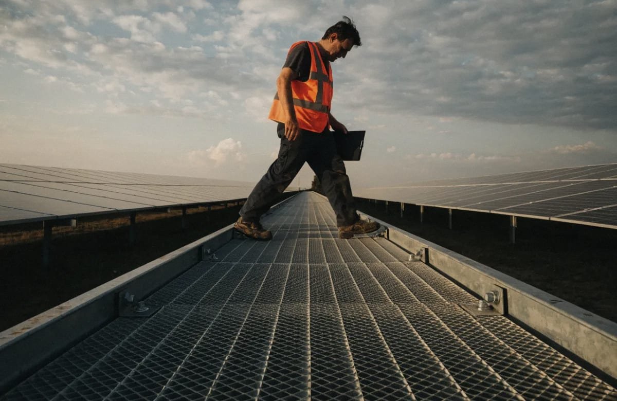
I learned the hard way that hot-dip galvanized steel grating can make or break a solar project’s long-term maintenance budget — and most buyers overlook it until problems surface.
To choose the right hot-dip galvanized steel grating for solar panel installations, evaluate zinc coating thickness for corrosion resistance, match load-bearing capacity to your mounting structure, confirm bearing bar spacing and serrated surface options, and verify the manufacturer’s compliance with ASTM A123 standards before ordering.
Many EPC contractors and project managers spend weeks evaluating PV modules and inverters solar mounting structure 1. But the maintenance platforms and solar farm walkways that technicians walk on every day? Those often get a single line item on the BOM. This article breaks down the four critical decisions you need to get right. Each one directly affects structural integrity, worker safety, and your total cost of ownership over a 25-year project life.
What Zinc Coating Thickness Do I Need for Long-Term Corrosion Resistance?
A project director in Singapore once asked me why two galvanized grating panels that looked identical failed at completely different rates. The answer came down to one number: zinc coating thickness — and the environment where each panel was installed.
For most outdoor solar installations, you need a minimum zinc coating thickness of 600 g/m² (about 85 µm per side) compliant with ASTM A123 or ISO 1461 to achieve 25-plus years of corrosion resistance. Coastal or high-humidity sites require heavier coatings up to 900 g/m².
How the Hot-Dip Galvanizing Process Creates Protection
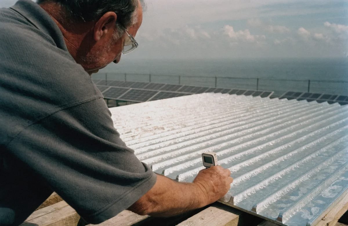
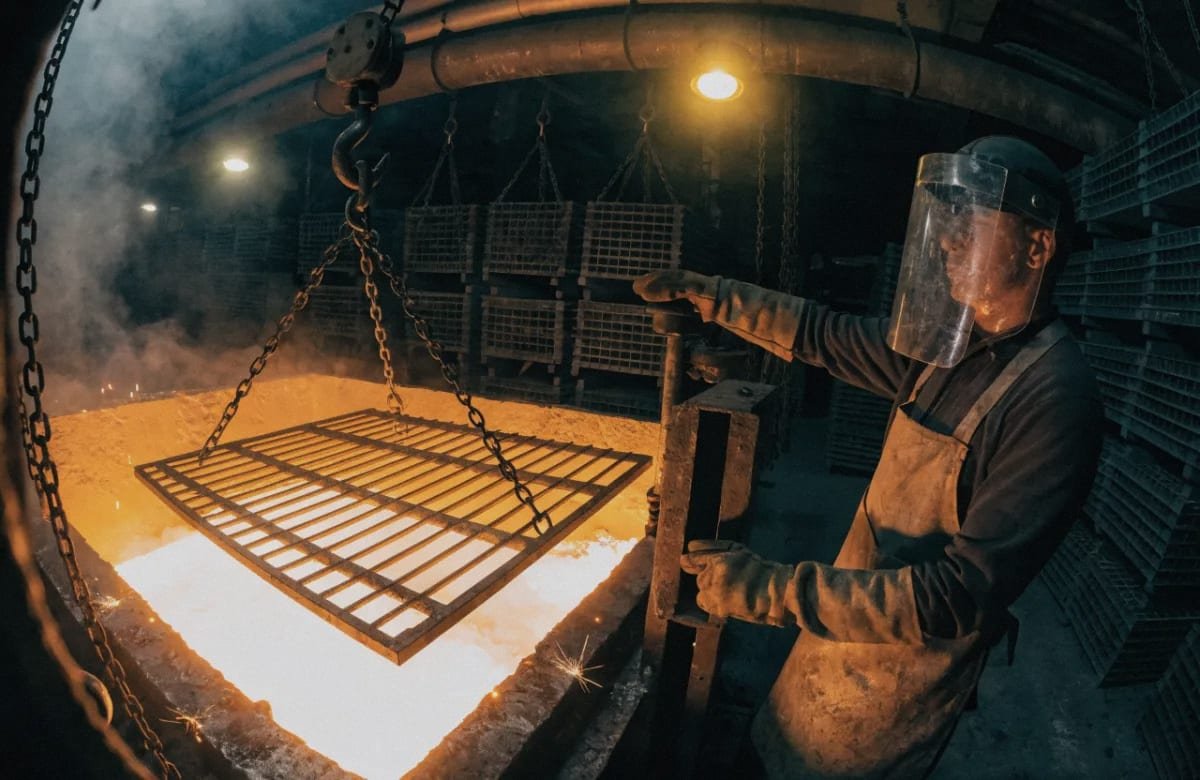
When we send steel grating through our partner galvanizing lines, the panels are submerged in molten zinc at roughly 450°C. This is not paint. The zinc reacts with the steel to form zinc-iron alloy layers that are metallurgically bonded to the base metal. You cannot peel this coating off the way you can chip powder coating.
This bond delivers three distinct layers of protection:
- Barrier protection. The zinc physically isolates the steel from moisture, oxygen, and pollutants.
- Cathodic (sacrificial) protection. If the surface gets scratched during transport or installation, the surrounding zinc corrodes first, sacrificing itself to protect the exposed steel.
- Self-healing. Zinc corrosion products fill in minor damage over time, sealing small scratches automatically.
Matching Coating Grade to Site Conditions
Not every solar project faces the same corrosion threat. A rooftop array in a dry inland city is very different from a ground-mount solar farm 500 meters from the coast. The ISO 9223 corrosivity categories help you choose the right zinc coating thickness.
| ISO Corrosivity Category | Typical Environment | Recommended Zinc Coating | Expected Service Life |
|---|---|---|---|
| C2 — Low | Dry rural or suburban inland | 500–600 g/m² | 40–50 years |
| C3 — Medium | Urban or mild industrial | 600–700 g/m² | 30–40 years |
| C4 — High | Coastal (1–5 km from shore), tropical humid | 700–800 g/m² | 20–30 years |
| C5 — Very High | Direct salt spray, heavy industrial | 800–900 g/m² | 15–25 years |
I always recommend that buyers share the project’s GPS coordinates and local climate data with us. We then cross-reference the corrosivity category and suggest a coating grade. Over-specifying wastes money. Under-specifying creates a maintenance gap where the grating fails years before the solar panels reach end of life.
Temperature Resilience
Hot-dip galvanized steel grating performs reliably from -40°C to +200°C. This range covers virtually every climate where solar panels operate. In desert environments, surface temperatures on exposed metal can exceed 70°C during peak sun. The zinc coating remains stable. In northern regions with harsh winters, the coating does not crack or delaminate. This thermal resilience is a key reason HDG is the industry standard for PV mounting systems and maintenance platforms.
How Do I Match Load Capacity Requirements to My Solar Mounting Structure?
One trade-off I weigh on nearly every solar grating order is this: heavier bearing bars increase load-bearing capacity but also raise material cost and shipping weight. Getting this balance right is essential.
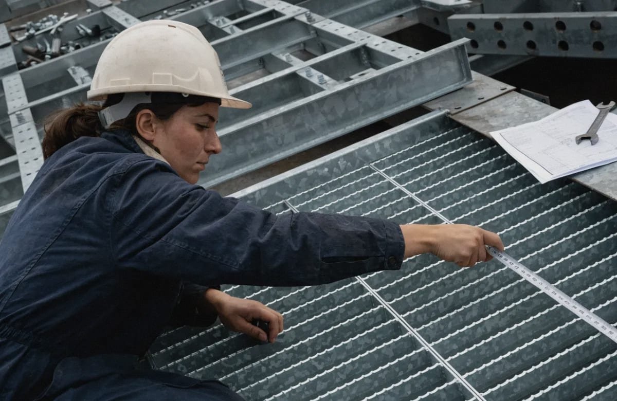
Match load capacity by first calculating the maximum span between structural supports, then selecting a bearing bar depth and spacing (typically 25×3 mm to 40×5 mm at 30 mm or 40 mm pitch) that meets the combined dead load, live load, and safety factor specified in your project’s structural design code.
Understanding the Loads on Solar Grating
Steel grating on a solar installation must handle several types of loads simultaneously:
- Dead load — the self-weight of the grating panel itself.
- Live load — the weight of maintenance technicians, tools, and occasionally heavy cleaning equipment.
- Dynamic load — impact forces from dropped tools or foot traffic.
- Wind uplift — in open-field solar farms, wind can create suction forces beneath elevated grating wind uplift 3.
For most solar farm walkways, the design live load ranges from 2 kN/m² (light foot traffic) to 5 kN/m² (heavy equipment access). Rooftop installations typically require less capacity because heavy machinery access is rare. But I have seen projects where a window-cleaning crane or fire-rescue team needs roof access, so always confirm the design load with the structural engineer before specifying grating.
Bearing Bar Dimensions and Span Tables
The load-bearing capacity of steel grating depends on three variables: bearing bar depth, bearing bar thickness, and the clear span between supports. Here is a simplified reference table based on common grating configurations we supply:
| Bearing Bar Size (mm) | Bar Spacing (Pitch) | Max Recommended Span | Suitable Live Load |
|---|---|---|---|
| 25 × 3 | 30 mm | 600 mm | Up to 2 kN/m² |
| 30 × 3 | 30 mm | 800 mm | Up to 3 kN/m² |
| 32 × 5 | 30 mm | 1,000 mm | Up to 5 kN/m² |
| 40 × 5 | 30 mm | 1,200 mm | Up to 5 kN/m² |
| 40 × 5 | 40 mm | 1,000 mm | Up to 4 kN/m² |
These values assume simply supported panels with a standard safety factor. For cantilevered or continuous-span applications, the numbers change. We always ask buyers to share their structural drawings so we can confirm that the grating specification matches the actual support layout.
Rooftop vs. Ground-Mount Considerations
For rooftop solar, weight matters. The building’s structural capacity limits how much dead load you can add. Here, high-strength, low-alloy steel or thinner bearing bars can reduce the dead load without sacrificing structural integrity. In some rooftop projects, I have seen engineers specify 25×3 mm bars at 40 mm pitch to keep weight below 25 kg/m².
Ground-mount solar farms have more flexibility. The steel substructure is purpose-built, so heavier grating is acceptable. The bigger concern is span distance. Wider support spacing reduces steel usage in the substructure but demands deeper bearing bars. This is a cost optimization exercise — and it is one reason we encourage buyers to discuss the full support structure design with us before locking in a grating specification.
Slip Resistance and the Serrated Surface Option
Worker safety on maintenance platforms is non-negotiable. A serrated surface on the top edge of each bearing bar provides essential grip in wet, oily, or dusty conditions. Smooth-top bars are cheaper, but they create a slip hazard that no responsible EPC contractor should accept. For solar farm walkways, I recommend serrated grating as the default. Some projects also specify “Grip Strut” or diamond-pattern expanded metal for areas with higher foot traffic or steeper inclines.
What Grating Specifications Should I Confirm Before Placing a Bulk Order?
A lesson I keep relearning: vague specifications on a purchase order lead to disputes at the port. Every dimension, finish, and accessory must be spelled out in writing before production starts.
Before placing a bulk order, confirm the base material grade (Q235 or equivalent), bearing bar spacing and depth, cross bar pitch, overall panel dimensions, zinc coating weight per ASTM A123 or ISO 1461, surface type (plain or serrated), and the specific clip or fastener system for your mounting structure.
The Complete Specification Checklist
Here is the checklist I send to every buyer before we finalize a grating order. Each item prevents a specific problem downstream.
| Specification Item | What to Confirm | Why It Matters |
|---|---|---|
| Base material grade | Q235B, S235JR, or HSLA equivalent | Determines yield strength and weldability |
| Bearing bar dimensions | Depth × thickness (e.g., 32×5 mm) | Controls load-bearing capacity |
| Bearing bar pitch | 30 mm or 40 mm center-to-center | Affects load distribution and weight |
| Cross bar pitch | 50 mm or 100 mm | Impacts drainage, debris passage, and panel stiffness |
| Panel length and width | Custom to project layout | Reduces on-site cutting and waste |
| Surface finish | Plain flat bar or serrated top edge | Serrated is required for slip resistance on walkways |
| Zinc coating standard | ASTM A123 4 / ISO 1461 | Guarantees minimum coating thickness |
| Zinc coating weight | e.g., 610 g/m² minimum | Matches corrosivity category |
| Edge banding | Flat bar or angle frame on panel edges | Provides a clean finished edge and structural rigidity |
| Fastening method | Saddle clips, bolted clamps, or welded | Determines installation flexibility and thermal expansion accommodation |
| Grounding provisions | Bonding lugs or dedicated earth points | Required for electrical earthing of the solar mounting array |
| Packaging and shipping | Bundled with protective spacers | Prevents zinc damage during transit |
Material Grade: Q235 and Beyond
Most solar grating uses Q235 low-carbon steel 5. It welds easily, galvanizes well, and costs less than alloy steels. For rooftop projects where dead load is critical, some engineers specify Q345 or an HSLA equivalent. The higher yield strength allows thinner bars to carry the same load, reducing weight per square meter.
Cross Bar Pitch and Drainage
Cross bar pitch affects more than just structural stiffness. On solar farm walkways, a 100 mm cross bar pitch allows rainwater and debris to pass through quickly. This prevents water pooling that could accelerate corrosion on the support structure below. It also improves ventilation under PV panels, which helps manage heat buildup and can benefit bifacial solar panel 6 performance by allowing reflected light (albedo) to reach the underside of the modules.
A tighter 50 mm cross bar pitch offers better support for smaller foot sizes and is sometimes required by safety codes. But it traps more debris and restricts airflow. I recommend discussing the trade-off with your design engineer.
Fastening: Clips vs. Welding
For outdoor solar installations, I strongly prefer bolted saddle clips over welding. Here is why. Steel expands and contracts with temperature changes. A welded connection is rigid — it resists thermal movement and can crack over time. Bolted clips allow small amounts of movement. They also make panel replacement easier during the project’s 25-year life. Use galvanized or stainless steel clips to avoid creating a galvanic corrosion 7 cell between dissimilar metals.
Acoustic Considerations
This one surprises many buyers. In open-field solar plants with high wind corridors, certain grating configurations can cause wind-induced whistling or resonance. The bearing bar orientation relative to prevailing wind direction matters. If your site experiences sustained winds above 40 km/h, raise this with your supplier early. Rotating the panel orientation or adjusting bar spacing can eliminate the problem.
How Can I Verify Quality Control Standards When Sourcing from a Chinese Manufacturer?
When a buyer in the Philippines told me he had received grating with zinc coating that flaked off during installation, I understood immediately — the galvanizing line had not cleaned the steel properly before dipping. Quality control failures like this are preventable, but only if you know what to check.
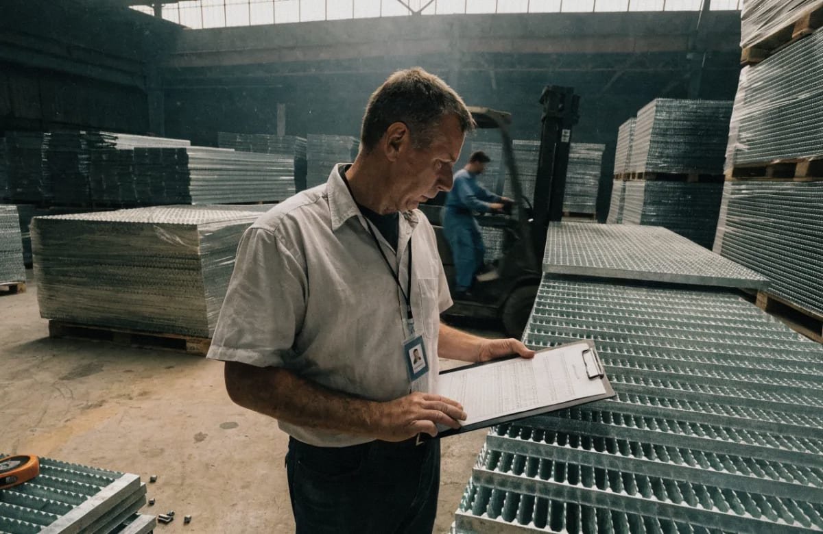
Verify quality control by requesting mill test certificates for the base steel, independent zinc coating thickness reports per ASTM A123, pre-shipment inspection photos and videos, and third-party inspection by SGS, Bureau Veritas, or equivalent before the container is sealed.
Step-by-Step QC Verification Process
Quality control is not a single checkpoint. It is a process that runs from raw material intake through final packing. Here is the sequence I follow on our production line for every grating order.
Step 1: Raw Material Verification. Before any cutting or welding begins, confirm the steel grade. Ask for the mill test certificate (MTC) from the steel mill. The MTC should show chemical composition and mechanical properties. Cross-check the steel grade against your purchase order.
Step 2: Dimensional Inspection During Fabrication. Bearing bar depth, thickness, pitch, and panel dimensions should be spot-checked during production, not just at the end. Request in-process inspection photos with a caliper or tape measure visible.
Step 3: Galvanizing Quality. After hot-dip galvanizing, the zinc coating thickness must be measured with a magnetic or electromagnetic coating thickness gauge. Measurements should be taken at multiple points on each panel — center, edges, and corners. The minimum reading, not the average, must meet the specified standard. Request the actual gauge readings, not just a “pass/fail” statement.
Step 4: Visual Inspection. The galvanized surface should be continuous, smooth, and free of bare spots, blisters, dross inclusions, and excessive roughness. A few small lumps of zinc are acceptable under most standards, but large drips or runs indicate poor process control.
Step 5: Pre-Shipment Inspection (PSI). Before the container is loaded, a comprehensive inspection covers dimensions, coating, quantity, packing, and marking. I recommend hiring an independent third-party inspector — SGS 8, Bureau Veritas, TÜV, or Intertek — especially for first-time orders or large quantities.
Red Flags to Watch For
Through years of exporting to Southeast Asia and South America, I have identified several warning signs that signal potential quality issues:
- The supplier cannot provide an MTC for the base steel.
- Zinc coating thickness is reported only as an average, not as individual readings.
- The supplier resists or delays third-party inspection requests.
- Packing photos show grating panels stacked without protective spacers, which causes zinc abrasion during shipping.
- The quoted price is significantly below market average — this often means thinner bars, lighter zinc, or both.
What ASTM A123 and ISO 1461 Actually Require
Both standards specify minimum zinc coating thickness based on the steel thickness. For example, ASTM A123 requires a minimum average coating thickness of 85 µm (610 g/m²) for steel thicker than 6 mm. ISO 1461 9 has similar requirements. These are minimums, not targets. A well-run galvanizing plant will consistently exceed them.
When you request compliance documentation, look for the specific clause reference (e.g., “ASTM A123-17, Table 1”) and actual measured values. Generic statements like “meets international standards” without data are meaningless.
Building a Long-Term Supplier Relationship
Quality control gets easier over time when you work with the same manufacturer. On our side, we keep records of every order’s inspection data, buyer feedback, and any corrective actions taken. This creates a quality history that both parties can reference. For repeat buyers, we already know their tolerances, preferred packing methods, and documentation requirements. This reduces errors and speeds up delivery — two pain points that project directors like our partners in Singapore care deeply about. Understanding how hot-dip and ordinary galvanized products differ in corrosion resistance can also help buyers set the right expectations during the QC process.
Conclusion
Choosing hot-dip galvanized steel grating for solar installations requires balancing zinc coating thickness, load-bearing capacity, detailed specifications, and rigorous quality control — decisions that protect your project’s safety and ROI for decades. If your project also involves cable management on the same structures, learning how to compare hot-dip vs electro-galvanized trough cable trays for performance and cost can help you apply consistent corrosion-protection logic across all galvanized components.
Footnotes
- Government resource detailing photovoltaic system components and mounting structures. ↩︎
- Background concept explaining the galvanizing process described in the article. ↩︎
- Background concept on wind loading forces relevant to grating structural design. ↩︎
- Primary standard specification for zinc coating on iron and steel products. ↩︎
- World Steel Association resource on steel grades referenced for grating material. ↩︎
- US Department of Energy resource explaining bifacial panel technology mentioned in article. ↩︎
- Explains the dissimilar-metal corrosion risk mentioned for fastener selection. ↩︎
- Official page for third-party inspection agency referenced for quality verification. ↩︎
- Official ISO page for the current 1461:2022 galvanizing standard. ↩︎
- Official corporate overview page for the global certification body. ↩︎