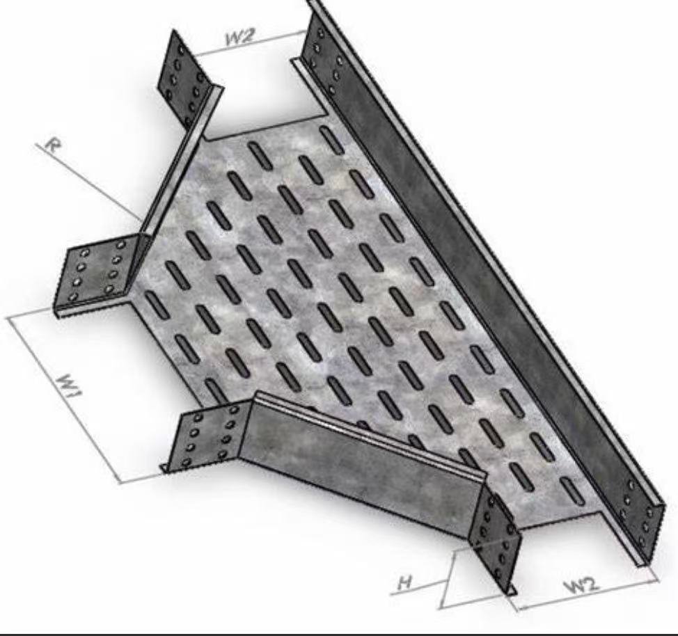
Every cable management system I’ve supplied for EPC projects lives or dies by the fittings that connect straight sections — the bends, tees, crosses, and reducers that route cables around corners, between floors, and through junctions.
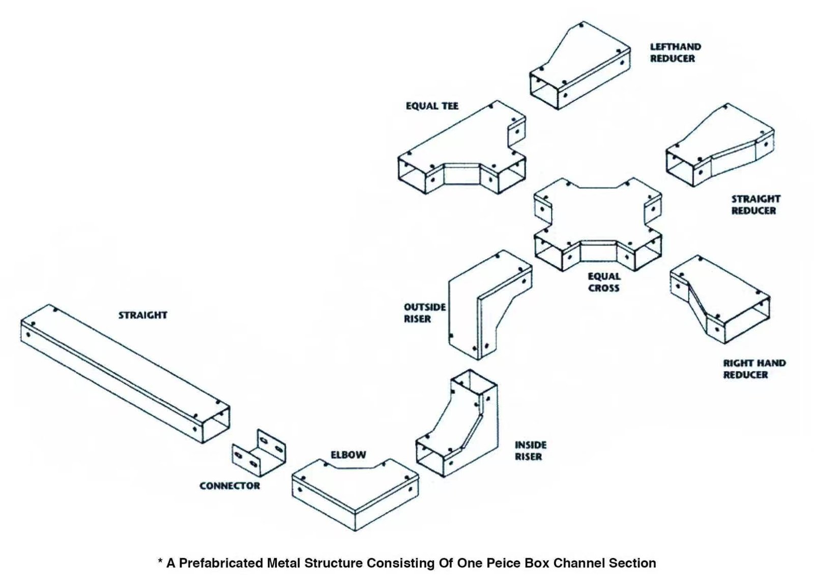
Cable tray fittings are geometry-correct components — including bends (horizontal and vertical elbows at 30°, 45°, 60°, or 90°), tees (three-way junctions), crosses (four-way junctions), and reducers (width transitions) — that change direction, branch routes, or adapt tray sizes while maintaining the safe cable bending radius and code compliance.
Each fitting type solves a specific routing problem minimum cable bending radius 1. Choosing the wrong one causes cable damage, installation delays, and expensive rework. Below, I break down every category, share practical selection guidance, and explain how we help project teams get exactly the fittings they need.
How do I choose the right cable tray bend for my project layout?
A project contractor in the Philippines once sent us a routing drawing with fourteen direction changes across a single floor fiberglass reinforced plastic (FRP) 2. That project taught me how much time proper bend selection saves — or wastes — on a job site.
Choose a cable tray bend by matching the required angle (30°, 45°, 60°, or 90°) and orientation (horizontal elbow or vertical riser) to your routing plan, ensuring the radius of curvature meets the minimum cable bending radius specified for the largest cable in the tray.
Horizontal Bends: Navigating Corners on One Level
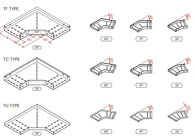
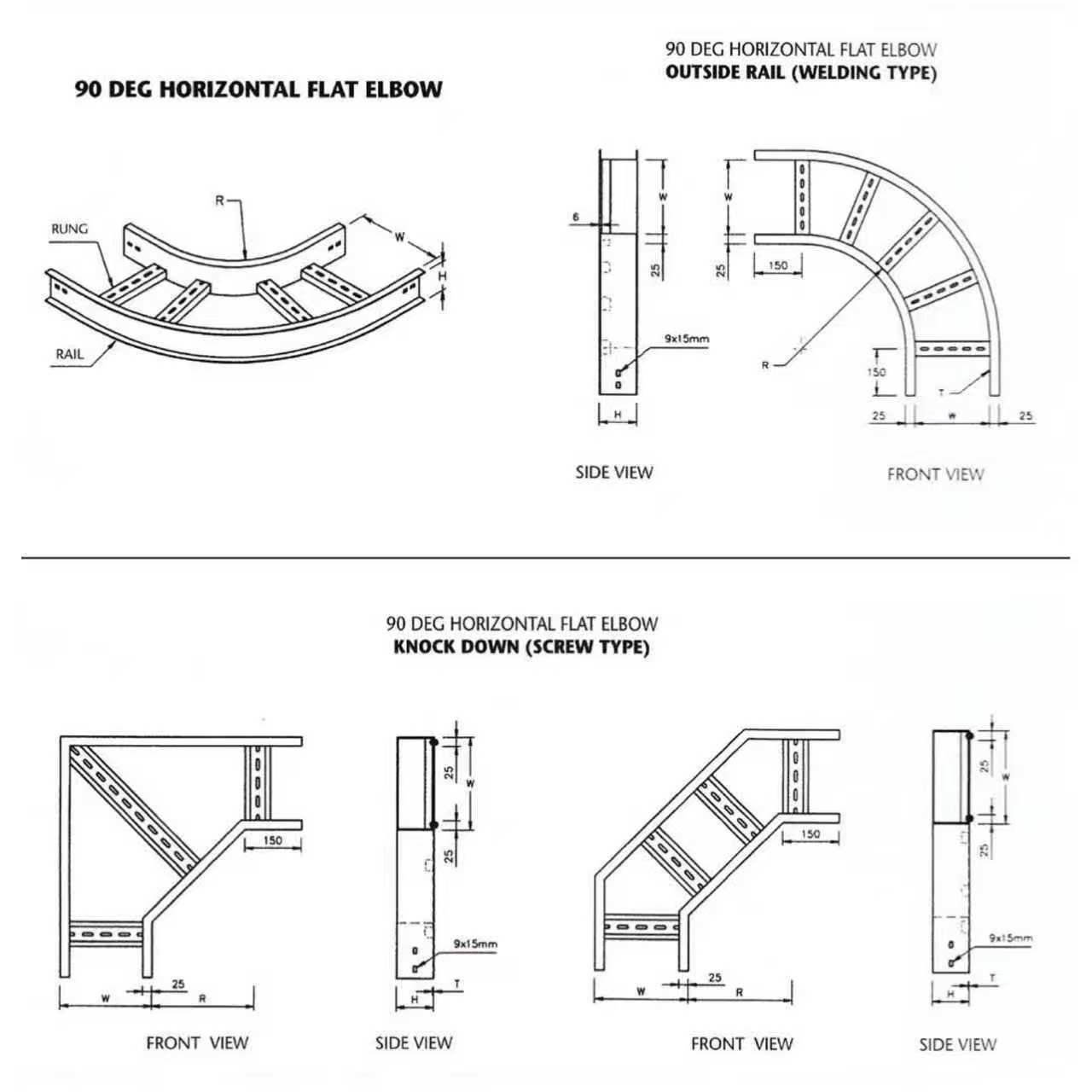
Horizontal bends — sometimes called flat elbows — let a cable tray turn left or right while staying on the same plane. Our production team fabricates these in four standard angles: 30°, 45°, 60°, and 90°. A 90° bend is the most common. It makes a clean right-angle turn, which suits most building corners. But in processing plants or solar farms, non-orthogonal routing is common. That is where 30°, 45°, and 60° bends become essential.
The bend radius matters more than the angle. A tight radius can force cables past their minimum bending radius, cracking insulation over time. Larger radii protect cable integrity but need more space. We typically recommend a radius equal to or greater than the tray width for standard power cables.
Vertical Bends: Changing Elevation
When a tray moves from one level to another — say, from a ground-floor rack up to a mezzanine — you need vertical bends, often called internal and external risers.
- Inside Vertical Riser (Riser Up): Curves the tray upward from a lower run to a higher run. The cable rides on the inside of the curve.
- Outside Vertical Riser (Riser Down): Curves the tray downward. The cable rides on the outside of the curve.
Mixing up inside and outside risers is a surprisingly common mistake. It leads to cables hanging unsupported or rubbing against sharp edges.
Quick-Reference: Bend Selection Table
| Bend Type | Plane | Standard Angles | Typical Use Case |
|---|---|---|---|
| Horizontal Elbow | Horizontal | 30°, 45°, 60°, 90° | Turning corners on the same floor |
| Inside Vertical Riser | Vertical | 30°, 45°, 60°, 90° | Routing tray from lower to upper level |
| Outside Vertical Riser | Vertical | 30°, 45°, 60°, 90° | Routing tray from upper to lower level |
Material and Construction Considerations
Every bend we produce matches the parent tray in material and finish. If the straight sections are hot-dip galvanized ladder cable tray, the bends are hot-dip galvanized ladder bends. Mixing materials — for example, putting a plain steel bend on an aluminum tray — creates galvanic corrosion 4 risk. We also supply bends for perforated trays, solid-bottom trays, and wire mesh basket systems.
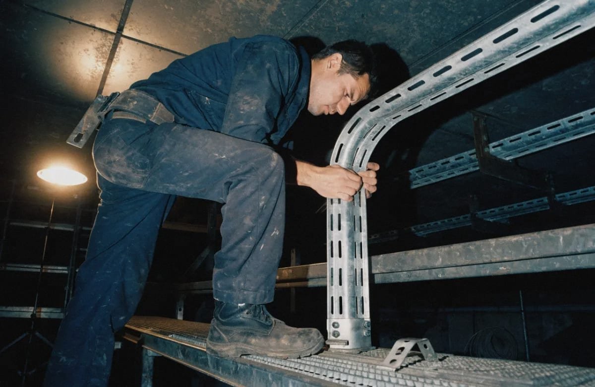
Support placement at bends is critical. Hangers or brackets should be installed within roughly 600 mm (about 2 feet) of the fitting on each side. Bends concentrate weight and torque, especially in loaded trays. Without close support, the joint can sag, loosen splice plates, or break grounding and bonding continuity.
Finally, I always tell project engineers: do not attempt to field-fabricate bends by cutting and welding straight sections. Pre-formed bends maintain the correct radius of curvature and load bearing capacity 5. Field-cut bends almost always create sharp edges, uneven surfaces, and code violations.
What’s the difference between a tee and a cross fitting in cable tray systems?
One question I get from procurement managers more than any other: “Can I just use a cross fitting everywhere instead of buying both tees and crosses?” The short answer is no — and here is why.
A tee fitting creates a three-way junction, branching one cable run off the main route at 90°, while a cross fitting creates a four-way junction, allowing two side branches to meet the main run at a single intersection point. Using the wrong one wastes material, space, and installation time.
Understanding Tee Fittings
A tee lets you split a single cable tray run into two directions — or merge two runs into one. Picture the letter “T.” The main run continues straight, and one branch exits at 90°. We manufacture tees for horizontal planes (standard horizontal tees) and vertical planes (vertical tee up and vertical tee down).
There is also a variation called the reducing tee. This joins two trays of different widths at the junction. For example, a 600 mm main run might branch into a 300 mm spur to feed a smaller equipment area. Without a reducing tee, you would need a separate reducer fitting plus a standard tee, adding parts, labor, and potential failure points.
Understanding Cross Fittings
A cross fitting is a four-way intersection. It connects four cable tray sections, all meeting at 90° in the same plane. Crosses are less common than tees but essential in large facilities with grid-pattern routing — think data centers, power plants, or water treatment facilities where cable routes run in both X and Y directions.
Like tees, crosses come in standard and expanding versions. An expanding cross joins trays of different widths at the intersection.
Side-by-Side Comparison
| Feature | Tee Fitting | Cross Fitting |
|---|---|---|
| Number of Directions | 3 (main run + 1 branch) | 4 (main run + 2 branches) |
| Junction Angle | 90° | 90° |
| Common Catalog Code | HT (Horizontal Tee) | HX (Horizontal Cross) |
| Reducing Version Available | Yes (RT — Reducing Tee) | Yes (EX — Expanding Cross) |
| Vertical Version Available | Yes (VTU / VTD) | Rarely needed |
| Typical Application | Branch spur off main run | Grid-pattern intersections |
When to Use Each
Use a tee when a single branch leaves the main run. Use a cross only when two branches need to exit in opposite directions at the same point. Installing a cross where a tee would suffice wastes material and creates an unnecessary opening in the tray that must be covered or managed.
In every cable management system, electrical continuity across fittings is mandatory. Both tees and crosses require splice plates and bonding jumpers at each connection point. Without proper grounding and bonding, the entire tray system fails to meet NEMA standards 6 and local electrical codes.
We also offer wye fittings (45° branches) for projects where a smoother, more gradual branch angle is needed. Wyes reduce cable stress at the junction and work well in runs carrying large-diameter power cables.
How do I know when I need a reducer fitting for my cable tray installation?
During a recent order for a water treatment plant in Thailand, the project engineer initially specified a single tray width for the entire run. After reviewing the cable schedule together, we identified three points where the number of cables dropped significantly — making wider trays unnecessary and costly beyond those points.
You need a reducer fitting whenever your cable tray transitions between two different widths — typically because the number of cables in the run increases or decreases at a branch point, equipment feed, or zone boundary — to maintain proper cable fill ratio and protect cables from abrupt size changes.
Why Reducers Matter
A reducer is not just a tapered piece of metal. It serves two engineering purposes. First, it provides a smooth physical transition so cables are not pinched, kinked, or forced around a sharp step. Second, it maintains the correct cable fill ratio 7. Running fewer cables in an oversized tray is wasteful. Running too many cables in an undersized tray overheats them.
Types of Reducers by Orientation
The orientation of a reducer determines which side of the tray stays straight (aligned with the wall, rack, or support). This is the detail that catches many installers off guard.
- Straight Reducer (HSR): Both sides taper symmetrically. The centerline of the tray stays in the same position.
- Left Hand Reducer (HLR): When viewed from the wide end looking toward the narrow end, the left side is straight and the right side tapers inward.
- Right Hand Reducer (HRR): When viewed from the wide end looking toward the narrow end, the right side is straight and the left side tapers inward.
The viewing direction matters. Always look from the wide end toward the narrow end to determine left or right. Our engineering team prints arrows on reducer drawings to prevent confusion. Getting this wrong means the tray does not align with your support structure, and you lose time and money on-site.
Types of Reducers by Geometry
| Geometry | Description | Best Use Case |
|---|---|---|
| Concentric | Tapers equally from both sides toward the center | Center-mounted trays, symmetrical routing |
| Eccentric | Tapers from one side only; the other side stays flush | Wall-mounted trays, runs needing flat-bottom continuity for drainage |
Eccentric reducers are common in chemical plants and outdoor installations where water must drain in one direction along the tray bed. Concentric reducers work well in overhead runs where the tray is centered on a support structure.
Practical Decision Process
Here is a simple three-step process I walk through with project teams:
- Check the cable schedule at each section. Count the cables entering and leaving each zone. If the count drops or increases, mark that point.
- Compare required tray widths. Use the cable fill calculation for each zone. If two adjacent zones need different widths, you need a reducer at the transition.
- Determine orientation. Look at the support layout. If the tray is wall-mounted on the left, you likely need a left hand reducer to keep the left rail aligned with the wall bracket.
Expansion joints 8 near reducers also deserve attention. Temperature changes in long runs cause the tray to expand and contract. Placing an expansion joint close to a reducer prevents stress from concentrating at the width transition.
Can I get these cable tray fittings customized and delivered on time for my project?
A project director in Singapore once told me his biggest fear was not price — it was receiving the wrong fittings two weeks after the installation crew had already moved to the next phase. That conversation shaped how our team handles every fitting order today.
Yes — cable tray fittings including bends, tees, crosses, and reducers can be fully customized in material, size, angle, and finish, and reliable manufacturers with dedicated production lines can deliver them within agreed lead times when specifications are confirmed early in the project planning stage.
What Customization Options Are Available?
Our production facility in Tai’an handles OEM and ODM orders for cable tray fittings across a wide range of parameters. Here is what we can customize:
- Material: Carbon steel, stainless steel (304 or 316) 9, aluminum, or fiberglass reinforced plastic (FRP) for corrosive environments.
- Surface Finish: Hot-dip galvanized, pre-galvanized, electro-galvanized, powder-coated, or bare for customer-applied coatings.
- Dimensions: Width, height, bend radius, and tray type (ladder cable tray, perforated, solid bottom, wire mesh basket).
- Angles: Any standard angle (30°, 45°, 60°, 90°) or custom angles for non-standard routing.
- Accessories: Pre-installed splice plates, integrated grounding lugs, and divider plates for phase separation.
How We Manage Delivery Timelines
Delivery delays are the number one pain point I hear from EPC contractors and wholesalers. We address this with a structured process:
- Early specification lock-in. We work with project engineers to finalize fitting specifications before production begins. Changes after production starts are the primary cause of delays.
- Batch production scheduling. Fittings are grouped by project phase and produced in batches that match the installation sequence. Phase 1 fittings ship first.
- Quality control checkpoints. Every fitting is inspected for dimensional accuracy, surface finish quality, and structural integrity before packing. This prevents returns — another major delay source.
- Logistics coordination. We arrange shipping to Southeast Asia, Africa, and South America with reliable freight partners and provide tracking information so project teams can plan crew schedules around actual arrival dates.
Key Factors That Affect Lead Time
| Factor | Impact on Lead Time | How to Mitigate |
|---|---|---|
| Late specification changes | Adds 1–3 weeks | Finalize specs before PO |
| Non-standard angles or sizes | Adds tooling setup time | Confirm early; share routing drawings |
| Surface finish (hot-dip galvanized vs. pre-galv) | Hot-dip adds processing time | Factor into schedule from the start |
| Order volume | Large orders need more production slots | Place orders in phases if schedule allows |
| Shipping destination | Transit time varies by region | Use sea freight for bulk; air for urgent items |
Material Matching and Quality Assurance
Every fitting we ship matches the straight tray sections in material, gauge, and finish. This is not optional — it is an engineering requirement. Mismatched materials cause galvanic corrosion, especially in humid or coastal environments. Mismatched gauges affect the load bearing capacity at the joint.
We also ensure all fittings meet the relevant NEMA standards for the tray class ordered. For projects requiring specific certifications, we coordinate testing and documentation before shipment. Our goal is simple: fittings arrive correct, on time, and ready to install — so the project stays on schedule and the installation crew never has to wait.
Conclusion
Cable tray fittings — bends, tees, crosses, and reducers — are geometry-critical components that protect cables, ensure code compliance, and keep installations on schedule when selected and sourced correctly from the start.
Footnotes
- Explains the engineering concept referenced for protecting cable insulation from stress damage. ↩︎
- Explains the composite material option used for corrosive environment fitting applications. ↩︎
- Background on the galvanization process used for corrosion-resistant tray fittings. ↩︎
- Defines the corrosion mechanism caused by mixing dissimilar metals in tray systems. ↩︎
- Explains the structural engineering concept critical to fitting joint design and safety. ↩︎
- Authoritative Wikipedia entry covering NEMA VE 1 and VE 2 cable tray standards. ↩︎
- ISO standards body relevant to cable tray sizing and fill capacity engineering practices. ↩︎
- Describes the engineering component that manages thermal expansion stress near reducers. ↩︎
- Background on stainless steel grades commonly specified for corrosion-resistant fittings. ↩︎