Last year, a project director from Singapore called me about rust forming on cable trays just eighteen months after installation at a refinery site — the wrong galvanizing process had been specified, and the entire cable management system needed replacement.
To choose GI ladder type cable trays for crude oil refinery projects, you must verify hot-dip galvanization with a minimum 100-micron zinc coating, confirm load capacity for heavy power cables, match tray dimensions to your routing layout, and ensure full compliance with IEC 61537 and NEMA VE 1 standards.
This guide walks you through every critical decision point NEMA VE 1 1. I will share what our production team has learned from supplying cable trays to refinery and petrochemical EPC projects across Southeast Asia and South America.
How do I choose the right galvanizing thickness for my ladder cable trays to withstand refinery corrosion?
A conversation with a Philippines-based EPC contractor taught me something I now repeat to every buyer: the galvanizing process matters more than the steel grade when your trays live inside a refinery for decades uniform distributed load 2.
For crude oil refinery environments, always specify hot-dip galvanized (HDG) ladder cable trays with an average zinc coating thickness of at least 100 microns. This level of corrosion resistance protects against chemical vapors, humidity, and salt exposure for 20 to 30 years without rusting.
Understanding the Three Galvanizing Methods
Not all galvanized finishes are equal. Many buyers confuse pre-galvanized sheet with hot-dip galvanized finished products safety factor 3. Here is a clear breakdown.
| Galvanizing Method | Zinc Thickness | Corrosion Life | Best Use Case |
|---|---|---|---|
| Pre-Galvanized (Mill Galvanized) | 20–40 microns | 5–10 years | Indoor commercial buildings |
| Electro-Galvanized | 8–25 microns | 3–7 years | Light-duty, dry environments |
| Hot-Dip Galvanized (HDG) | 80–120 microns | 20–30 years | Refineries, petrochemical plants, outdoor industrial |
Pre-galvanized trays use sheet steel that was coated before fabrication ASTM A123 4. When you cut, punch, or weld that sheet, you expose bare steel at every edge and joint. In a refinery, those exposed spots become rust points within months.
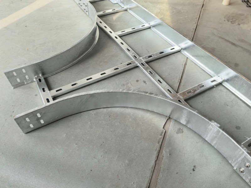
Hot-dip galvanization 5 works differently. We fabricate the tray first — cut, punch, weld — and then dip the entire finished product into molten zinc at around 450°C. This coats every surface, edge, bolt hole, and weld seam. The result is a seamless zinc barrier with no weak points.
Why 100 Microns Is the Refinery Standard
From our experience shipping to refinery projects, anything below 80 microns fails within a decade in a typical crude oil processing environment. The atmosphere inside a refinery contains hydrogen sulfide, sulfur dioxide, and moisture. These chemicals attack thin zinc layers aggressively.
At 100 microns average thickness, the zinc layer provides both a physical barrier and cathodic protection 6. Even if the surface gets scratched during installation, the surrounding zinc sacrificially corrodes to protect the exposed steel. This self-healing property is why hot-dip galvanization outperforms paint and powder coating in harsh environmental conditions.
When GI Is Not Enough
I must be honest: GI ladder trays are not suitable for every zone in a refinery. In areas with direct acid splash, continuous chemical immersion, or offshore coastal exposure, you need stainless steel cable trays — typically Type 316. For zones classified under hazardous area classification 7 standards where non-sparking surfaces are required, FRP cable trays or aluminum may be necessary.
However, for the vast majority of refinery process areas, utility corridors, and pipe racks, hot-dip galvanized steel delivers the best balance of cost and durability. Our customers consistently choose HDG because it provides roughly 80% of the corrosion protection of stainless steel at about 30% of the cost. For a deeper comparison of coating methods, see our guide on how to compare hot-dip vs electro-galvanized trough cable trays for performance and cost.
What structural load capacity do I need for my GI ladder trays to safely support heavy refinery cabling?
When we were developing load-test procedures for a large petrochemical project order, I realized that many buyers underestimate the combined weight of medium-voltage power cables running through a single tray section — and they almost never account for the weight of a maintenance technician standing on top.
Your GI ladder trays must support the total uniform distributed load of all cables (often 50–150 kg per linear meter for heavy power runs) plus a concentrated point load of at least 100 kg for maintenance access. Always calculate load capacity based on the specific span length between supports and include a safety factor of 1.5 to 2.0.
How to Calculate the Required Load
Load capacity calculation is not complicated, but it requires accurate input data. Here is the process I walk our buyers through:
- List every cable that will run through the tray, including future expansion cables.
- Get the weight per meter for each cable from the cable manufacturer’s datasheet.
- Add all weights to get the total uniform load in kg/m or N/m.
- Add the concentrated load — a minimum of 100 kg (or per your project specification) applied at the midpoint of the span.
- Apply the safety factor — typically 1.5 for normal areas and 2.0 for critical zones.
- Check against the tray’s rated working load at the specified span length.
Sheet Thickness and Its Impact on Strength
The steel sheet thickness directly determines how much weight a tray can carry. For refinery projects, we typically supply trays in 1.6 mm, 2.0 mm, and 2.5 mm thicknesses. Here is how they compare:
| Sheet Thickness | Typical Working Load (at 2m span) | Recommended Application |
|---|---|---|
| 1.6 mm | 80–120 kg/m | Instrumentation cables, light control wiring |
| 2.0 mm | 150–200 kg/m | Medium-voltage power cables, mixed cable runs |
| 2.5 mm | 250–350 kg/m | Heavy power cables, main feeders, high-density runs |
These values depend on the rung spacing, side rail height, and the grade of steel used. But as a general rule, never use 1.6 mm trays for main power cable runs in a refinery. The minimum I recommend for any process area is 2.0 mm.
Span Length Matters
A tray rated for 200 kg/m at a 2-meter support span will carry significantly less at a 3-meter span. Longer spans increase bending moment 8 and deflection. In refinery pipe racks, support spacing can vary from 1.5 m to 3.0 m depending on structural steel availability. Always confirm the load rating at your actual span length — not just the best-case number on a datasheet.
Side Rail Height and Rung Spacing
The depth of the side rail (typically 50 mm to 150 mm) and the spacing between rungs (typically 200 mm to 300 mm) also affect structural performance. Deeper side rails resist bending better. Closer rung spacing distributes cable weight more evenly. For heavy refinery cabling, I recommend a minimum side rail height of 100 mm and rung spacing no wider than 300 mm.
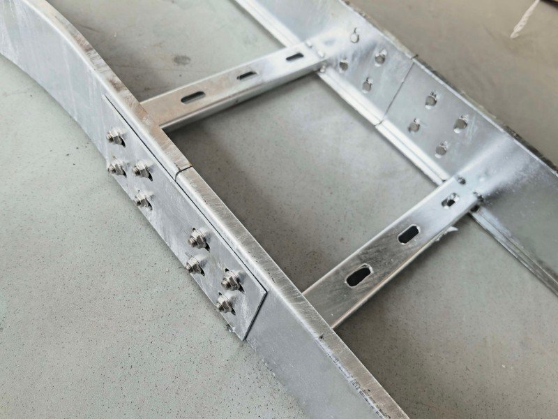
Cable tray grounding is another consideration tied to structural design. The tray system must maintain electrical continuity 9 across every joint and splice. This means splice plates must be properly bolted with lock washers, and bonding jumpers should be installed where specified by your electrical engineer. A well-grounded tray system prevents stray voltage hazards and meets IEC 61537 10 requirements.
How can I customize the dimensions and accessories of GI ladder trays to fit my specific refinery layout?
One lesson I learned early in this business: no two refinery cable routing layouts are the same. Even within a single plant, the path from the main control room to the process units involves horizontal runs, vertical risers, T-junctions, and bends at angles that rarely match standard catalog items.
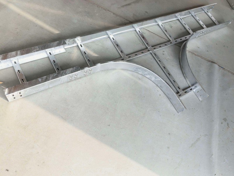
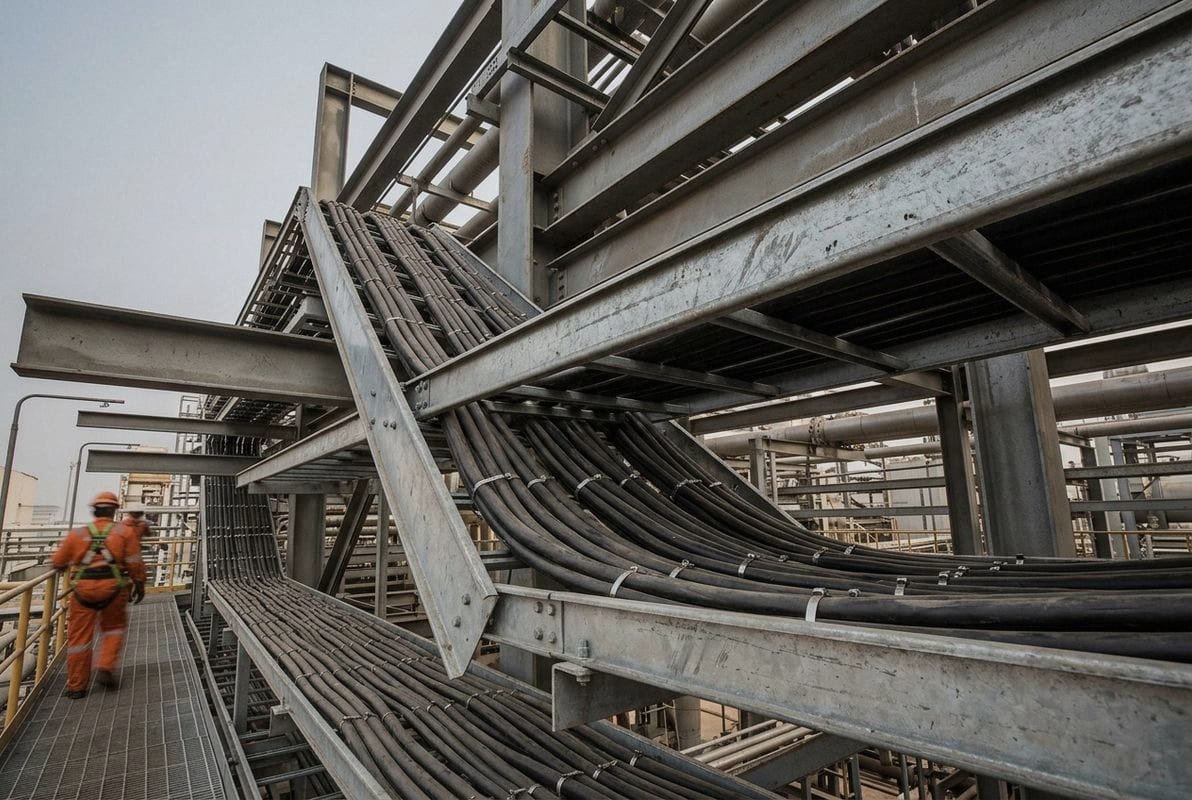
You can customize GI ladder tray dimensions — including width (150 mm to 1200 mm), height (50 mm to 150 mm), and length — along with fittings like horizontal bends, vertical elbows, T-junctions, reducers, and splice plates to match your exact refinery routing. Working with a manufacturer that offers OEM/ODM services ensures every piece fits your layout precisely.
Standard Dimensions vs. Custom Sizing
Most GI ladder trays come in standard widths. But refinery projects often need non-standard sizes. Here is a reference table of common dimensions:
| Parameter | Standard Range | Common Refinery Specs |
|---|---|---|
| Width | 150 mm – 1200 mm | 300 mm, 450 mm, 600 mm, 900 mm |
| Side Rail Height | 50 mm – 150 mm | 75 mm, 100 mm, 150 mm |
| Rung Spacing | 200 mm – 300 mm | 250 mm (most common) |
| Standard Length | 2400 mm – 6000 mm | 3000 mm, 6000 mm |
| Sheet Thickness | 1.6 mm – 2.5 mm | 2.0 mm, 2.5 mm |
When a buyer sends us a cable schedule and routing drawing, we can calculate the exact tray width needed. The general rule is that cables should fill no more than 40–50% of the tray cross-section. This leaves room for heat dissipation and future additions.
Essential Fittings and Accessories
The straight tray section is just the beginning. A complete cable management system for a refinery requires a full set of fittings. Here is what our production line typically supplies for a refinery project:
- Horizontal bends (30°, 45°, 60°, 90°) — for changing direction along a pipe rack
- Vertical elbows (inside and outside risers) — for going up or down between elevations
- T-junctions — for splitting cable routes at branch points
- Cross-junctions — where two routes intersect
- Reducers — for transitioning between different tray widths
- Splice plates — for connecting straight sections end-to-end
- Cover plates — for protecting cables from falling debris or sunlight in specific zones
- Support brackets and hangers — wall-mount, ceiling-mount, and trapeze types
Every fitting must match the tray width, height, sheet thickness, and galvanizing specification. A 90° horizontal bend for a 600 mm wide tray is a different part from one for a 450 mm tray. This is where OEM customization becomes critical. We fabricate fittings to match the exact tray profile so joints are flush and secure.
Fire Protection and Special Coatings
In certain refinery zones, fire protection requirements demand additional treatment. Cable trays may need fire-resistant wrapping or intumescent coatings that expand when exposed to heat, forming an insulating char layer. This maintains circuit integrity for 20 to 30 minutes during a fire event, meeting API and OISD standards.
The open ladder design of these trays is excellent for heat dissipation during normal operation. But that same openness can allow fire to spread along the cable route. Fire barriers and fire stops at wall and floor penetrations are essential installation guidelines that your contractor must follow.
For dusty areas within the refinery, some engineers prefer adding removable covers or selecting trays with partially closed rung designs to prevent dust accumulation on cables.
What quality control steps should I require from my supplier to ensure my GI ladder trays meet project safety standards?
A buyer from Thailand once returned an entire container of cable trays because the zinc coating peeled off during installation. The root cause was simple: the factory had skipped the acid-pickling step before dipping, so the zinc did not bond properly to the steel surface. That experience shaped how we run every quality checkpoint on our production floor today.
Require your supplier to provide material test certificates, verify zinc coating thickness with a calibrated gauge (minimum 100 microns for HDG), conduct load testing per IEC 61537 or NEMA VE 1 standards, inspect dimensional accuracy, and perform visual inspection for surface defects before shipment.
The QC Checklist Every Refinery Buyer Needs
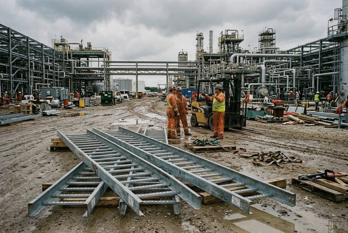
Quality control for refinery cable trays is not optional. A failure means cable damage, fire risk, or costly replacement during plant operation. Here is the inspection process I recommend requiring from any supplier:
Step 1: Raw Material Verification. Ask for mill test certificates for the steel coil. Confirm the steel grade (typically Q235B or equivalent), sheet thickness, and yield strength. Do not accept trays made from unknown or recycled steel without proper documentation.
Step 2: Dimensional Inspection. After fabrication, measure the tray width, height, rung spacing, and length against the approved drawing. Tolerance should be within ±2 mm for width and height. Check that bolt holes align with splice plates and fittings.
Step 3: Galvanizing Quality. This is the most critical step for refinery projects. After hot-dip galvanization:
- Measure zinc coating thickness at multiple points using a magnetic thickness gauge. Require a minimum average of 100 microns with no single reading below 80 microns.
- Check for bare spots, drips, rough areas, or zinc ash inclusions.
- Confirm that the galvanizer followed proper pre-treatment: degreasing, acid pickling, and fluxing before dipping.
Step 4: Load Testing. For critical projects, request a load test report. The tray should be tested at the specified span length with the rated working load applied uniformly. Deflection must stay within allowable limits — typically L/100 (span divided by 100) under working load.
Step 5: Packing and Shipping Inspection. Trays must be bundled and packed to prevent damage during transit. Check for protective packaging between layers, secure strapping, and proper labeling. Damaged zinc coating during shipping defeats the purpose of HDG.
Standards You Should Reference
Your purchase specification should call out at least one of these standards:
- IEC 61537 — the primary international standard covering mechanical strength, electrical continuity, and corrosion resistance for cable trays
- NEMA VE 1 / VE 2 — widely used in US-influenced projects; defines dimensions, load ratings, and testing methods
- ASTM A123 — specifies zinc coating thickness requirements for hot-dip galvanized structural steel
- IS 5 / IS 2629 — Indian standards commonly referenced in Southeast Asian and Middle Eastern refinery projects
When we prepare documentation for an EPC order, we include material certificates, zinc thickness test reports, dimensional inspection records, and photographs of the finished product. This paper trail gives the project engineer confidence that every tray arriving on site meets the approved specification. For guidance on how to verify custom fabrication for hot-dip galvanized trough cable trays, we have a dedicated resource covering the full inspection workflow.
Avoiding Common Supplier Pitfalls
Many suppliers quote hot-dip galvanized but actually deliver pre-galvanized trays. The price difference is significant — HDG costs more because of the separate dipping process. If the price seems too low, ask questions. Request a factory visit or a third-party inspection. Insist on seeing the galvanizing facility.
Another common issue is inconsistent sheet thickness. Some factories use thinner steel than specified to cut costs. A simple caliper measurement during inspection catches this immediately. Always verify thickness on the finished product, not just the raw material certificate. If you are sourcing from China, our guide on how to choose the best hot-dip galvanized ladder cable trays covers what to look for when evaluating manufacturers.
Conclusion
Choosing GI ladder type cable trays for crude oil refinery projects comes down to four decisions: specify hot-dip galvanization at 100 microns minimum, calculate true load capacity, customize dimensions to your layout, and enforce strict quality control at every stage.
Footnotes
- Explains the US standard for metal cable tray systems, including construction and load testing. ↩︎
- Educational resource from Engineering Statics providing a clear definition and explanation of uniformly distributed loads. ↩︎
- Wikipedia provides a comprehensive and accessible definition of the factor of safety in engineering. ↩︎
- Details the standard for hot-dip galvanized coatings on iron and steel products. ↩︎
- Explains the process and benefits of hot-dip galvanization. ↩︎
- Explains the electrochemical process of cathodic protection for corrosion control. ↩︎
- Defines the process of identifying areas with flammable or explosive atmospheres. ↩︎
- Defines the internal force that causes a structural element to bend. ↩︎
- Explains the concept of an unbroken electrical path for current flow. ↩︎
- Official IEC standard page for IEC 61537:2023, providing authoritative information. ↩︎